Monday, November 23

Installing Rasbpian with Noobs


You bought yourself a shiny new Raspberry Pi, maybe the brand new Pi Zero and now you are really fidgety about doing something exciting with it but ... there are a few things that need to be done first.

I have provided three complementary videos that you can watch to go through the entire process or if you prefer you can go through the following brief instructions

This is in a nutshell what needs to happen:


  • Get an SD card
  • Format the SD card
  • Transfer NOOOBS onto the card
  • Boot your Raspberry Pi with NOOBS
  • Select and install the Operating System

The first thing you need to do is to get yourself an SD card with a suitable Operating System installed on it so that the Raspberry Pi can run all the basic software that is needed for it to do anything.

At this point NOOBS is your friend!

NOOBS is a piece of software that will help you installing the Operating System onto the SD card.

This can go either of two ways:


  1. Buy a card with a preloaded NOOBS on it
  2. Reuse one you already own and prepare it with NOOBS yourself.

The preferred Operating System for the Pi is Raspbian and its latest incarnation is called Jessie. The names of the versions of this OS are coming from Toys Story, the previous one in fact was called Wheezy!

Now Wheezy's character was a bit chubby and Jessie's was quite slim in the cartoon but despite this you will need a bigger SD card to store Jessie than you would have with Wheezy as the OS Jessie is a bit bigger than its predecessor. With this in mind make sure you use at least an 8 GB SD card for your Pi.


  • Follow this section only if you are reusing you card


If you are going to reuse your card you have to first format it or in other words prepare it to be able to transfer NOOBS onto it, to do so you can use a software called SDFormatter. It is a really easy install to perform and you can use the videos provided if in doubt.


Make sure to backup the contents of your SD card before proceeding as the tool will delete all files in it

Select the right drive letter corresponding to your SD card and click on Format. You will have to accept a couple of alert messages and you card will be ready shortly after.

Once the card is formatted you will need to transfer NOOBS on it. First of all let's get hold of NOOBS.


Once downloaded (it will take a while) it will have to be unpacked in a temporary folder of your choice.

With the content unpacked you will now have to select all the files and copy/paste them onto the SD card you have just formatted (that also will take a while).


The card is now ready to be ejected from the card reader and plugged into the Raspberry Pi.


  • Whether you have used your own card or purchased one with NOOBS pre-installed this is what needs to happen next


Make all the necessary connections to the video, the network, the mouse and keyboard and finally plug the power supply in.

After a short while you should lend onto this page


Select install near to Raspbian and ... after a while and a few rather useful information displayed during the installation, the process will terminate and prompt you for restarting into Rasbpian for the very first time.

Great! You made it, your Raspberry Pi is now ready for many adventures to come

Here are the embedded videos mentioned above

HW preparations to get started

Prepare the SD card, get hold of Noobs and transfer it onto the card

Connecting all up and install Raspian


Friday, November 20

Electronics Recycling Dumpster Diving

I have been very surprised time and time again every time I would go to the recycling centre by the amount of good quality things that get thrown away on a regular basis. Each time I would visit to dump I have always find time to have a peek at the electric and electronic appliances skip.

It is amazing to notice how people overcome their imposed limits and would pick things up as well as chuck their stuff away. Especially on a weekend there will be even some habitué who would always be at the recycling centre to be sure never to miss the best "donations" of the day and I thought : "Why not?" Why shouldn't we all do that without inhibitions and in fact with some sense of pride. "I recovered something from the garbage and gave it a second life"

It is a win!, win^2! loose?
It is a win for me as I get something for free.
It is a double win for the environment as the item doesn't need to be created again just for me and doesn't need to be destroyed. Destroying is the counterpart of creating and it is the counterpart of the costs that are not quite taken into account when giving a value to an item as it hits the market. Destroying or in the best case recycling costs money in the act of collecting and transforming our "garbage" and worse of it all, leaves a heritage to the future generations that will have to find a way to deal with it, most probably with additional costs.
It is a loose for industry maybe. Well industry needs to modernise itself and find a different way to survive, why not re-purposing items and reselling them?

Rant apart, here is the video of what I found at the recycling centre and the hurdles I had to overcome to get my bounty.


Thursday, November 19

Electronics Recycling at the local Charity Shop

Every Tuesday morning a volunteer helps the local charity shop to PAT test all electrical donations. On Tuesday afternoon I would be visiting the shop to see what goodies has the generous community given away.

In October I found a nice Kensignton laptop stand which came connected to a WiFi USB card from Netgear.

In the video below I went through this £5 purchase to see what could be salvaged and what could be chucked away.

Sunday, November 1

Halloween Automated Scarer 2015

A pinch of pygame, a hint of scapy and the Halloween concoction is ready!

This year's automated scarer was a bit more challenging than last. I stitched this together in a couple of days and ... it worked mostly as I wanted it to be. The most important thing is that children and parents enjoyed being scared by a few monstrous pumpkins and a bunch of my son's very horrific (but beautifully made) drawings.
Raspberry thirsty Vampire
Scary Witch of the South East

I wanted the animation to be easy to be activated and yes, I could have used other methods to detect people to be scared (which from now on I will refer to as scarables: a person suitable for the scarer) but I was curious about scapy and the possibility of detecting mobiles passing by.


I also found quite interesting digging through the enormous amount of information available on pygame which served perfectly the purpose of displaying the pictures and playing the sounds all of this without needing to drop into X leaving ample resources available on my RPi B

It is also entertaining to lookup the MAC addresses I collected to establish if we live in a posh area or not. The amount of Apple devices wasn't so many in the end, I will consider selling and buy elsewhere.
Ah and don't worry, the MACs I collected will be handed over to TalkTalk for safe keeping.


The Python script revolves mainly around the scapy command sniff which I used to search any broadcasting WiFi device within reach of my dongle.
The first thing to do is to setup the WiFi card into monitor mode which is done outside of python on the shell:

#/usr/bin sh
sudo service ifplugd stop
sudo ifconfig wlan0 down
sudo iwconfig wlan0 mode monitor
sudo ifconfig wlan0 up
sudo service ifplugd start

You can verify things are set properly by issuing iwconfig, this is my output:

wlan0     IEEE 802.11bgn  Mode:Monitor  Frequency:2.412 GHz  Tx-Power=20 dBm
          Retry short limit:7   RTS thr:off   Fragment thr:off
          Power Management:off

Within scapy's lamda function we need to create a list to hold the MAC addresses that we'll acquire. Around the area where I live there are normally quite a few Access Points and other WiFi devices. The first thing to do then is to store all these MACs on a file so that they will not trigger any false "scares" each time that the Pi starts. I did this by running the script in "silent mode" for a couple of hours. I had created in this way a WiFi fingerprint of the area which I stored on a file that gets read at the start of the script and pre-loads all the MACs in the neighbourhood.

if path.isfile(fileName):
    with open(fileName, 'rb') as MAC_file:
        MAC_list = pickle.load(MAC_file)

for the serialisation I am using pickle which for the purpose works just fine

From here on any new MAC detected is a potential scarable,

Scapy offers a sniff command that can take as arguments an interface and a function amongst other options.

sniff(iface = "wlan0", prn = PacketHandler, store=0)

The store=0 turned out to be vitally important as it tells the sniff command to just monitor the packets and not store them in memory. I learned this the hard way as I the Pi stopped responding all together as its memory got full.
I have obviously specified to monitor packets on wlan0 and given a PacketHandler function which I use to specify what I am interested in about the packets seen by wlan0

def PacketHandler(pkt):
        if pkt.haslayer(Dot11):
                if pkt.type == 0:
                        if pkt.addr2 not in MAC_list:
                                MAC_list.append(pkt.addr2)
                                with open(fileName, 'wb') as MAC_file:
                                        pickle.dump(MAC_list, MAC_file)
                                        Call the Scare function

the layer I am interested in is Dot11 as in 802.11x and the packet type is 0 as in management. If the MAC is not in my list I will add it and write the list on a file.
The other very important thing that I do in the last if block is that I will start the animation for each new MAC added to the list.
Now, this could have done it in a number of ways, I wanted to explore the pygame events, I wanted to use two threads on for WiFi scanning the other for the animation, in the end at 16:30 of the 31st of November I decided to call a function directly after writing the list to a file.

image = images[random.randint(0, len(images)) - 1]
sound = sounds[random.randint(0, len(sounds)) - 1]
Scare(image, sound, screenSize)

The Scare function receives a random image and a random sound from two preloaded lists. I paste the PrepareImages only as the PrepareSounds is essentially the same

def PrepareImages():
        imagesNames = glob.glob('*.png')
        imageCache = []

        for imageName in imagesNames:
                try:
                        imageCache.append(pygame.image.load(imageName).convert())
                except:
                        raise UserWarning, "Could not load images"

        return imageCache

All .wav and .png files where in the same path as the script.
Everywhere I looked for examples of pygame.image.load I found that it is highly recommended to convert the images to improve performance. I certainly noted an improvement

The Scare function looks like this

def Scare(image, sound, screenSize):
        image = pygame.transform.scale(image, screenSize)
        frame = image.get_rect()
        white = (255, 255, 255)
        black = (0, 0, 0)
        screen = pygame.display.set_mode(screenSize)

        playing = sound.play()
        while playing.get_busy():
                screen.fill(white)
                screen.blit(image, frame)
                pygame.display.flip()
                pygame.time.delay(1000)
        screen.fill((black))
        pygame.display.flip()

it will resize the picture (sometimes deforming it as the source did not have the same proportions of the screenSize I selected), set the screen, play the sound.
Whilst playing the sound the picture would be displayed (blit) and a 1 second delay also added to get the shivers deep in the scarable's spine.
After the sound is played the screen turns black again.


That's it really, ciao!


Tuesday, December 2

Ghetto ESXi server

How would you like to transform your sluggish desktop based hypervisor into a super fast server based one?


Well in fact maybe I have exaggerated a tiny bit, you are not going to transform a desktop PC into a blade server but ... the end result is pretty neat considering that for the majority is free and fairly easy to achieve.

I have had for quite a while a PC at home continually powered on and running a bunch of virtual machines. The hardware is nothing spectacular:
  • Intel Core i5 750 (1st Gen)
    • 64 bit 
    • Intel® Virtualization Technology (VT-x) 
  • 6 GB of RAM
  • Sata disks
  • 3 NICs (one Realtek and two Intel)
that's it really but it is enough to fulfil the minimum requirements to run ESXi. The full list of supported hardware is available via the VMware compatibility matrix.

The biggest trouble I had with my system was that it ran Window 7 Home edition and Oracle VirtualBox for the virtualisation platform. Don't get me wrong, VirtualBox is great, the trouble though is having a full blown OS like Windows underneath which needs updating, chews a lot of RAM on its own, gets all sorts of security issues, etc. One can use Linux I guess to get less of a footprint and it works better as a server in many ways but the bulk of the problem pretty much stays.
If you have ever used VMware ESXi I really don't need to sell this to you, it is designed to be a great hypervisor and many will consider it simply the best.

So I had this idea brewing for quite a while to see whether I could install the standalone version of ESXi onto my PC, take all my VMs and convert them to VMware. Turns out that last week I managed to just that!

Creating the ESXi image

The first problem to solve was to get an image that will work with the hardware I had. For most of what I have done below I followed the instructions on this blog.
  1. Download the base image from VMware. I got my ESXi 5.5U1 from this link
  2. As my PC has a realtek card and ESXi 5.5 does not have drivers for it,
  3. Download the ESXi customiser to inject the drivers in the base image
  4. As an optional step I also wanted to use a USB key to perform the installation instead of a CD. The utility is called Rufus and can be downloaded here. This site also explain quite well how to use the utility.
With all of the above done I then had a USB key with a customised imaged for my bare metal hypervisor"to be.

After setting the BIOS to boot from the USB key I just followed the rather easy installation process for ESXi. The last step of it is to setup the management network which will then give you access from the vSphere client which can be found here

That was it for the installation, I might go through the configuration in a further post. The only problem I am having so far is to do with the chassis fan which is currently running at max speed as I guess the ACPI drivers aren't compatible with the mainboard. I will buy a quite fan to replace mine with.

In the next post I will go through how to convert and move the VMs from my VirtualBox to my new shiny hypervisor.


Friday, October 31

Halloween Automated Scarer part 2

And so this is the scarer in a box, all finished and connected up ready to spring into action


by either using the QR code or send an SMS to my Nokia 7250i the Python code will parse the incoming SMS. If the message says "scare" it will tell the PIC to scream. The PIC will be scared via its serial port and will then activate the motor back and forth a few times


Once installed in place the motor is linked to four fishing lines two are wound clockwise and two counter-clockwise. What is attached to the lines weighs pretty much the same on each and because they are wound in opposite direction the motor doesn't have to struggle much at all.


That's it really, the code isn't terribly interesting but I would be glad to provide it if needed.
Here is a short video of the final effect.


And this is the sign I had outside my house.


In the end I did not have many customers scared but quite a few took the time to watch the animation and enjoyed the novelty. A witch was particularly interested in the QR code, not even her could think of such sorcery!

Friday, October 24

Halloween Automated Scarer part 1

Me and the family are having great fun this year preparing the Halloween project. I am afraid this time we might have had exaggerated a bit but ... I guess it is too late now, we are nearly done!

Before I upload any pictures of the real thing and, who knows, maybe even a scary video, here is just a teaser.


Neighbours and children hungry for chocolate ... prepare to be scared wohahaha,


wohahaha,

wohahaha 

Thursday, October 9

IPEXPO second day

Day 2 IPEXPO 2014 Excel London

Before leaving home today I checked the weather forecast. It was mostly sunny and I thought it was a good omen. So there I was on my way to the second and last day of IPEXPO.


My resolution for the day was not to go to any of the talks in fear of the experience from the previous day.
I arrived "slightly" early at 8:00 o'clock when the gates would have opened at 9:30. At least that gave me time to catch up with some work and think of what I wanted to get from today's visit.

It was still sunny when they finally let us in. I knew that today it would have been the last opportunity for exhibitors to get business cards and contacts from the visiting crowd. The race was on!
I got approached already by somebody right at the entrance 30 seconds before 9:30. First beep of the day. Just so that it is clear, each one of these exhibitors was equipped with a bar code reader and my badge had a bar code that would say who I was. So as you are talking to somebody you would see them more or less discretely pull one of those "weapons" out of their pockets and with nonchalance ... they would beep you to death!
It was constant, you talk to somebody you get beeped, they give you a gadget but you get beeped, you go to a talk you get ... beeped, you get stopped by somebody that actually asks you information and ... you get BEEPED!! Well I guess you get it by now, there was no escaping.
As the hours passed it was rather entertaining to see visitors dodging pretty girls holding chocolate and gadgets in one hand and the dreadful weapon in the other. "Get a chocolate! Beep! mwahahaha".

Then there were the freebies freaks. They are a different species, lurking in the shadow they wait until all exhibitors are busy with other visitors to launch themselves in an attach magpie style and get their object of desire. Which in itself is rather sad especially if you consider that since the credit crunch the freebies you get are along the lines of pens and sweets. Who uses that many pens nowadays anyway!

My determination not to go to talks paid off in the end. Getting from one exhibitor to another wasn't easy but I eventually managed to have a good nearly old fashion chat with a few techies (yes they do still exist).

I had a really interesting chat with somebody from Ruckus which explained how different their antennas are from the competition and how does that guarantee a better coverage with less interference and eventually better bandwidth per user. Read this white paper for more.

My main goal for the day was to get more information on mobile users management for the enterprise and my best bets where Citrix and VMware's latest acquisition Airwatch. The acquisition is so recent that the guys from VMware and the guys from Airwatch were actually in two different stands!

Both seem to be offering similar solutions but Citrix seemed to be able to offer a wider scope of functionalities. They were also the only ones that could explain a bit more of what really happens in the back-end, what services need to be deployed, how does the admin GUI looks like and gave a rather in depth explanation of what happens on the mobile device that wants to join ... your private Cloud.

And so it ended. The first day was cloudy with a chance of content, the following day was dodge the beep but it was in fact more useful than the day before.

Am I going next year?

Wednesday, October 8

IPEXPO first day

Day 1 IPEXPO 2014 Excel London

Today was the opening day for the IPEXPO Europe which takes place in London Excel.
This was my first time at the IPEXPO and I did not know what to expect so ... bear with me if I did not get the full gist of it.


The event started with a rather refreshing speech from Sir Tim Berners-Lee. I had forgotten how difficult it is to follow what he says, I guess having your brain running at the speed of light causes some problems with the coordination of the lips. You should really film him and watch him later in slow motion to get all he his saying. Literally a river of words!

I guess the most difficult part to make sense of was about how could it really be possible for big corporations to shape up the future of the web to improve our life and guarantee democracy, I am afraid I was not terribly convinced about the ethics behind the likes of HP, Google, Microsoft, VMware, etc. and how are they going to give us back control on our data and our privacy but mostly how are they going not be tempted to use that same data for things like targeted advertising.
Well, his forecast is for 2050 and ... I believe in miracles and I want to believe in you Sir Tim Berners-Lee!
It was however really nice to listen to him talking about the beginning of the World Wide Web and how his boss Mike Sendall at CERN defined his proposal "Vague but exciting". It was 25 years ago and much happened in the meantime, maybe Mike Sendall was ahead of his time and had already thought about the future we live in today where everything is vague but exciting only we chose a better way to describe it:
The Cloud!
SERIOUSLY! Isn't time to stop abusing that word? The Cloud? What does it mean? Really? When I first heard about it I thought it was going to be a question of a year or so and people would have rebelled to that. Years later we are still using it and the technologies that are described behind the term are as cloudy as the promises they make. Even speakers are embarrassed to use it, they might have one of those clouds on the slides they are presenting but they make their best to actually try to use a different more meaningful word for it. Some might refer to grid computing, some may talk about hosting and so on.
I think cloud was really invented to sell something that had not really been quite developed yet or maybe they thought we could not handle the complexity of what they where offering and hid it behind ... well, behind something sort of foggy so that each one of us could see what they really were looking for.
YOU CAN'T HANDLE THE TRUTH 
And so the day went between colourful clouds and little icons moving back and forth to the clouds like little angels.
I am a system administrator at heart and a wannabe geek, back in the days what excited people was seeing a demo of something actually doing things. In the 90s seeing a GUI would give you a feel of what could be achieved with one program or another, seeing a shell ... well, seeing a shell and some scripting in action would get lads howling. Now you get clouds and pretty pictures, you are told a really nice story and frankly with pretty pictures and clouds you can say anything you want without risking too much.
"Say, where do the data go after they are uploaded to that system?"
"To the cloud"
"What will the users connect to when subscribing to that service?"
"To the cloud"
"Where are my servers and how do I administer them"
"Via the cloud"
and so on ...

Honestly I attended a few talks today and I could not quite understand what was that they were selling or more in general talking about. It all sounded like the c word, reduced TCO and yada, yada, yada.
Sometime I am wondering:
"Has information technology lost it?"
These mega vendors are selling us a new era of computing born out of their competition to sell products which are often rushed on the market without having reached the necessary maturity on both their design and their development and I feel as if at times we are no longer sold software, we maybe sold
CLOUDS!

Tuesday, October 7

Canon IXUS i5 stuck on movie mode


A few days ago I gave my children a Canon IXUS i5 that stopped working a while back. It had always bothered me that it could not be fixed and the more I would see them play with it the more it got me thinking that the problem it was suffering from was neither mechanical nor to do with the electronics.

I had that camera a few years ago from a friend which had asked me to look at it as it seemed to be stuck in movie mode despite which position was the selector in. Replay was movie mode, photos was movie mode.
Very annoying!

It had to be with the firmware and there had to be a way to either reset it or flash it anew.
I opted for the easy way first and tried to reset it. As you can imagine no mention of this on the manual and most upsetting not much on the internet either!

Electronic toys generally have a combination of buttons or keys that can be used to enter hidden features one of which can sometimes be a reset. About an hour later it was clear that this approach was not going anywhere, the camera has 9 buttons so it should have taken me longer but the more obvious combinations i.e. power button + menu, power button + function and some others weren't really promising.

I then decided for a radical approach; take it a part! (© Dave Jones)

It is a shame not to have taken any pictures of the process but frankly ... is it really worth to anybody knowing the step by step process to repair such an old camera?

To cut the story short, after removing the rather obvious screws, you get to expose the main PCB which sits on the front of the camera. Remove all the flat cables and get the PCB free. On its reverse you will find the tampon battery. Remove that for a couple of minutes (maybe much less) and job done! After putting the camera back together the camera is reset to factory settings and the problem is gone.

Little I new that this is pretty much the same procedure to get rid of the "Memory card error" affecting the IXUS 400 and apparently other models of the same family.

Well, this might not be of much help to many but certainly was of great satisfaction to me.

Sunday, May 25

0xEE.net is live!


Myself and Chas from /PNW/Electronics had been working on a new site where we join forces to produce a set of unique tutorials and articles on Microchip PICs, MikroC and XC8 compilers and a variety of protocols and devices that will be used thought the various articles.
0xEE.net has gone live with a couple of articles this weekend with more to come soon.
Have fun reading!

Sunday, May 18

Windows 8 - mikroElektronika USB18F Device - code 52

after spending far too much time with a code 52 which would not let the driver work, I run the following to disable the driver signature enforcement in Windows 8.1.

On an elevated CMD to disable:
bcdedit -set loadoptions DISABLE_INTEGRITY_CHECKS
bcdedit -set TESTSIGNING ON

to reanable:
bcdedit -set loadoptions ENABLE_INTEGRITY_CHECKS
bcdedit -set TESTSIGNING OFF


To check what are the current settings run bcdedit on an elevated cmd

Be aware that although I had installed the drivers when the driver signature enforcement was off, as soon as I enabled it once again the drivers where back to not working with code 52.

Despite many guides which will advice you to follow the GUI approach to achieve a one off startup with the driver signature enforcement, this seems to be a quicker and more permanent solution.
This is certainly not an ideal solution but a good enough workaround.


Update:

Mikroelektronika has now released new drivers which fix the problem. They can be found at this link

Thursday, May 15

The Mikro compilers for the Makro projects


Mikroelektronika is celebrating 10 years of compilers this month and I thought I should not be shy from joining the celebrations.
It was in fact 2004 when they decided the world  needed better compilers. Back then in order to get your LEDs blinking, on pretty much any microcontroller on the market, it wasn't as easy as it is today.
Ten years forward in time and now, thanks to the professionalism and dedication of Mikroelektronika's developers, we can now just simply click on an icon and your program get's compiled, programmed onto the microcontroller of your choice and executed, fantastic!
The code does not compile or something nasty is happening with the behaviour of your program? The compilers are coming with simple and intuitive debugging functionalities including In-Circuit Debugging. With it is possible to step by step through your code as it runs on the microcontroller which gives you the possibility to discover problems that only surface due to the program running on your circuit.

Some of the numbers of the Mikro guild are:
3 different languages for the various tastes - MikroC, MikroBasic, MikroPascal
6 different microcontroller platforms - PIC, dsPIC, 8051, AVR, PIC32, ARM
2 different licencing models - The traditional key installed on a computer and the more innovative USB dongle option for licencing on the go. Great flexibility.
785 and counting libraries available through LIBSTOCK to make the most of reuse of code. Any developer should share his/her code here! Seriously!!

The many libraries that come along with the compilers are very well documented, integrated with examples and in most cases with circuit diagrams. Should that not be enough, Mikroelektronika also offers a number of books and articles which in most cases are also available online for free. Although some of these need to be refreshed, they are still an excellent resource for the beginners and a good reference for the experts

The IDE has nothing to envy from the likes of MS Visual Studio or Eclipse. The MikroC for PIC page shows some of the functionalities and tools that are made available to the developer for efficient and effective coding.
Have you ever had to setup the fuses on a PIC16F84A prior to the Mikro era? With the Mikro IDE it is as simple as using the Edit Project.
Code assistant, parameter assistant, code folding? Need I say more? If you have done any coding in your life you know that you cannot live without these things.

An IDE should be a tool that helps the developer to get from a project to a program in the easiest and quickest possible ways. It is good and well to learn the hard way how to write your "Hello, world!" program or how to manually setup the fuses the first time, the second, even a third time but after that it becomes evil! A developer needs tools that will help him/her to quickly go through what should be a given and focus on the problem that matter to get the next project running and it seems to me that the Mikro compilers do just that. Isn't that the reason for the great success of the likes of the Arduino entourage?

Happy birthday Mikros and keep up the good work guys!

P.S. Can I get a piece of cake now?

Saturday, June 22

Embedded Linux Made Easy - restore gnublin image to SD card

Messing up the SD card is part of the game when playing with the Embedded Linux board from Elektor.

Elektor's official way of restoring the image to the SD card is by use of the Ubuntu system you are meant to work on when following the tutorial.

you can find the SD image file zipped at the Elektor website

as explained in the README file within the zip archive, to transfer the gnublin.img to the SD card, you have to issue the following command from Ubuntu:

sudo dd if=PATH_TO_SD_CARD_IMG_FILE of=/dev/SD_CARD_ID

for me it was:

sudo dd if=gnublin.img of=/dev/sdb (note it is sdb not sdb1 or sdb2, the image is for the whole card to but written bit by bit)

My Ubuntu is a VM, I use Oracle Virtual Box and there is no problem connecting the SD card reader to it. I have noticed though that it takes a really, really, really long time before the image is transferred to the card.

dd if=gnublin.img of=/dev/sdb
3854336+0 records in
3854336+0 records out
1973420032 bytes (2.0 GB) copied, 4999.44 s, 395 kB/s

this is 1.38 hours!!! I admit there is something quite wrong here which I mean to investigate further. It would seem that all of the three USB 2 SD card readers are seen as USB 1.1 by the VM.

In the meantime though if you want to do this very quickly you can use the same tool that it is used with the Raspberry Pi images. You can easily find it at the official site or here. (Note: remember to run the tools with administrative right otherwise it might not be able to write on your card)


It is slightly cheating on the "Linux purism" that Elektor tries to impose but ...

Wednesday, June 5

File transfer between a PC and an embedded system over the serial port

I was playing with the Elektor Linux board and needed to tranfer code compiled on a "host" system to the SD card of the embedded Linux board. Following the tutorial off the magazine I read:
"To test whether the above process has been successful, we can copy
the file ‘hello’ that the compiler has created to the Elektor Linux
board’s SD card. Make sure the board is off and remove the card.
Insert it into the PC’s card reader, and plug the reader into the PC."

I did not have a card reader with me and I did not like to halt the system, remove the card, etc. etc.
Back in the days of modems it was not unusual to transfer files over the serial ports.

This is what you need to do in order to transfer your files between your Linux PC and your Linux embedded system using the serial port.
Picocom can transfer files using several protocols that, whomever used to use modems, will be familiar with.
Specifically you can use ZModmem which is the best choice compared to XModem and YModem.

Enough with the yada yada, let's cut to the chase.
Let's say that you are either using Ubuntu or Mint for what matters.

You will need to install rz and sz. Check here for more.
apt-get install lrzsz

Your serial port is ttyUSB0.
Run: picocom -b 115200 /dev/ttyUSB0
Note the output especially:
send_cmd is     : sz -vv
receive_cmd is  : rz -vv
This means that your board can talk ZModem!

Hit ^a (ctrl+a) then ^s (ctrl+s). Read the man page for picocom to know more.
This will set picocom in file transfer mode. You will be prompted for a file name as follows:
*** file:
Write the full path of the file e.g. /root/hello (being the compiled version of hello.c)
Sure enough your next ls command should show the file now on your Elektor Linux board.

Tuesday, March 6

EasyPIC v7 review

What's new and what isn't

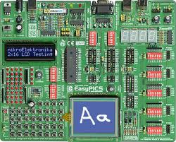
In this article I will review the new EasyPIC v7 development board from Mikroelektronika. I will compare it to the previous version, will look at the new design, take you through what is on board and what is no longer there and finally give you a general overview of it.

I really do not believe Mikroelektronika needs any more publicity on the EasyPIC v7, but I felt it would be nice to go through reviewing the new board my way and most importantly compare it with its predecessors!
Now, I am not going to compare them since the beginning of time, also because I jumped on board of the EasyPIC wagon only as of version 5, but I think it is nice to visually analyse the evolution of the board across  the various versions it went through. Quite an impressive progression really! The quality of photography too :)


EasyPIC2 EasyPIC3
EasyPIC4 EasyPIC5

EasyPIC6 EasyPIC7

Layout considerations
 
The designers of these great boards will hopefully forgive me if the considerations in this section may sound quite superficial, but I would first of all just give simply a visual impression of the various layouts without going in the details of why from an engineering point of view things were placed here or there. So with this in mind this is what I see:

It is interesting to notice how the various elements did and did not move from board to board. The layout of the EasyPIC2, 3, 4, 5 and 6 did not really change too much overall especially when compared to Version 7 which is without doubt the exception.

Led and buttons have always been bottom left but not in version 7 in which they have been placed in the ports area on the right.

The chip sockets more or less had been kept in the centre. One thing of note is that the EasyPIC5 as well as v7 have enough space for my trusty 40 pin zif socket to fit in. The EasyPIC6 would not allow it because the switch above the socket was really too close.

EasyPIC5, 6, 7 40 pin sockets side by side
EasyPIC v7 with zif socket
EasyPIC5 with zif socket


The ports were top to bottom on the right, quite so in version 7 too but now you have two connectors and a proto header per port plus another connector per port on the left! No wonder, their theme for this version is connectivity!

The LCD spot of the EasyPIC 2 was taken by the GLCD in the EasyPICS 3,4,5 and 6 sending the LCD towards the top left area. I presume the GLCD was also the reason why the form factor as of the EasyPIC3 became bigger. Whereas the LCD is quite in the same place on version 7 too, the GLCD has taken the place of the buttons and led.

With regards to size wise apparently the boards are growing over time. The EasyPIC5 measured 25x21 cm, the EasyPIC 6 and v7 are both 26.5x22 cm.

The on-board programmer and the power section area made it to the version 7 keeping the same spot. Interestingly the on-board programmer has now a "warranty void if removed" shield. I am not sure I like it, even in the manual it is represented as a "black box". Could this be for copyright?

The external communication connectors have also kept their space exception made for the serial port which as of version 6 is in the top left corner.

The 7 segment display was "less lucky" it travelled quite a bit and at one point it made it off the board entirely. Welcome back in v7!

Similar sort had the DS1820 which every time was really placed where there was space left.

The AD converter trimpots have remained pretty much where they were from version 2 to 5 and to 6 although in this version one was removed. In version 7 they have been moved together with the other two trimpots for the GLCD and LCD in a column next to the displays area.


A more rational design

As you can understand by now, version 7 was quite revolutionary in its design. It grouped elements in functional areas much more than any of the previous versions and sacrificed some gadgets that were introduced in version 6, towards usability and a rational layout.

EasyPIC v7
EasyPIC6
EasyPIC5
The switches area is also all in one place, exception made for the new tristate port switches. I am sure this arrangement, along the lines of the grouping of displays and trimpots, will be much appreciated especially by beginners.

I haven't used the new board too much yet but it looks to me that after a bit of readjusting my habits to the new layout it should be much easier to use. It shows some radical re-thinking of the board which must have taken some major effort and courage from Mikroelektronika. I am sure it will pay of.

Having port connectors to the left and to the right is really nice, you can now spread your work on each sides of the board. Often you have far too many things on the right of the board  when you are working with complex projects and several accessory boards. Having port connectors on the left will surely help to have a much neater workbench.


What is and was on board


The new board comes with the usual PC keyboard, USB and serial port connectors and the Ext ICD provided as of version 6. A notable new addition is the new UART via USB based on the FT232RL chip. I would not be surprised to see the RS232 disappear from a future version 8 but I certainly hope it doesn't. Dinosaurs like me grew to love it and might be difficult to part from the good old connector.

At the end of his EasyPIC6 review Roman  makes a list which in part turns out spookley prophetic!
According to him the perfect board should have had amongst other things:

2 AD converter trimpots as in the past versions
A piezo buzzer
An I2C eeprom


... and as if by magic you find all of the above on the EasyPIC v7! I couldn't agree more, those things were needed and are a welcome addition.


Another addition is the LM35 socket for an analogue temperature sensor, was it really needed?  I am not entirely sure but if anything it is another way of using the ADC and it does not take too much space.


The theme of connectivity Mikroelektronika has provided the EasyPIC v7 with five time as many ways of connecting accessory boards, prototypes and what have you to their five base ports.
Five ways because each port headers is replicated twice on the right and once on the left of the board,  plus on the proto connector. Last but not least the new mikroBUS sockets, something new and unique to this generation of boards.
EasyTEST
EasyPIC v7 port group
The only doubt I have here is whether the two port headers on the right were necessary at all time or if maybe a couple of EasyTEST would have been enough when needed.

EasyPIC v7
mounting hole
EasyPIC v7
GND point
With a workbench in mind and certainly for an educational setup, version 7 added four mounting holes to the corners of the boards. Nice touch!

Anybody who has done any measurements on the previous boards would certainly welcome the additional GNDs point, this is something I have personally been waiting for. Much appreciated indeed.


EasyPIC5 DIY spacers
EasyPIC v7 plastic spacer
Attention to details made so that as of the EasyPIC6 a couple of plastic display spacers were installed on the board. This was indeed a nice addition especially when using the touch screen for the GLCD without resorting to diy as I did for my EasyPIC5.


The dramatic redesign of the board came with some sacrifices and claimed some victims.
The menu and the 4x4 keypads, the port expander and the COG display had short life. Newly introduced in version 6 they have already disappeared. Let me attempt to guess why that was and how can one live without.
EasyPIC6 keypads
Keypad 4x4 board
With regards to the keypads I can see two possible reasons to why you really do not need to have them on board. The first is that an Keypad 4x4 Accessory Board is available if you really need to develop applications that need those keypads. Having it on board at all time was probably not needed. The second is that UIs are shifting to touch screen and one could make use of the GLCD more and more instead of using the buttons. Either ways I don't think too many people are going to be missing the two keypads too much.


EasyPIC6 COG
EasyPIC v7 with COG
The COG has been removed in favour of the return of the 7 segment display. I must agree with Gavin from MCU Store here, the replacement had probably been triggered by the fact that educational establishment love teaching multiplexing and strobe of I/O lines. Roman made a good point with regards to using the COG as a debugging display when using the main LCD as the normal output of the application. Personally, when possible, I tend to use the serial port as a way to do debugging over a terminal, if anyway you feel you cannot do without the COG there is now an accessory board COG 2x16 LCD Board which brings it back on one of the many port headers available on the EasyPIC v7.
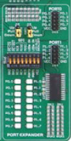

EasyPIC6 Port Expander
Port Expander Board
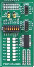
The other missing element is the port expander. I fully support the decision to remove them to make more space and rearrange the board in such a nice way. As for the previous elements there is a Port Expander Board and the new Expand Click that can be added should you need further connectivity to the one already provided!

Expand Click

I hope by now I have convinced EasyPIC6 owners to upgrade to v7. The new board has a few element less than the previous one but all there was can be added if needed. Some of the things added to the current version are unique to it and make so that the board is more professional, usable and expandable than each previous version ever was.


The EasyPIC v7

I bought my EasyPIC v7 from MCU Store which is the UK distributor for Mikroelektronica's products and had a really nice and friendly chat with the owner Gavin, asking for his personal view on the new board in light of writing this article. He kindly provided a few good points, not a surprise giving his knowledge of this kind of products. Amongst his comments he pointed me to the EasyPIC6 review from Roman Black which I would really invite you to read and was an excellent source of material for this review.

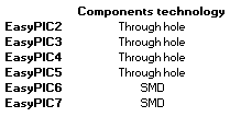
The EasyPIC6 introduced the SMD technology which contributed to a neater and more compact design. With the EasyPIC v7 this is taken to a further level. Click Boards are all SMD and through hole technology is gradually disappearing from the rest of the more traditional accessory boards.


How does it feel
The board is build to last and gives the impression of being quite sturdy in general, the buttons feel nice to the touch, they make a clicking noise when pressed and are to me of better quality then in previous version. With regards to buttons, the reset has been moved to the top right corner of the board far away from other buttons and in my opinion in a better position to avoid pressing it accidentally.
EasyPIC v7 tristate switch
The new tristate switches allow for pull-up/down or disable for each pin. Disable a single pin was not possible before. I find them a bit too small and fiddly to use with just the fingers which I could with the previous version of dip switches, you will probably need a pen or some tool to set them. On the contrary of what I thought it is pretty easy to put them in the middle position. Overall however the previous type of switch, which is still use on board for the configuration of the board, felt better to use.
I had to send back the first board I received because one of the trimpot knobs was broken, which can happen, but most annoyingly the LCD one was really quite loose and when measured it turned out to be faulty. The values on the ohmmeter where jumping all over the place when adjusting the resistance.The new board I received is fine but the trimpots still feel quite loose, maybe it is just a bad batch and hopefully the majority of the boards will be fine.
EasyPIC v7 dip switch
The LCD and the GLCD have not changed, the backlight though has and it is now possible to choose between Standard or PWM driven!


Documentation
 
The documentation provided is, as always, of really good quality. Incredibly detailed and really easy to go through. For those who are not familiar with the board they would be able to get up to speed with it in no time.
In writing this review I have noticed however that for this version of the board there are practically no high resolution pictures like there were for the EasyPIC5. I think it is a shame it is no longer available and hope Mikroelektronika might reconsider adding it again.

EasyPIC5 Layout

The schematic is absolutely excellent, I would really love if it were printed on a single page to "plaster" on the wall and keep as constant reference.
The package also includes a CD with all the software needed for you to start working with the board. To be in line with the excellent material provided in the box, all the software present on the CD I have received was up to date.
Some of the new aspects of the EasyPIC v7 have already been listed above, a radical new design , new components and the connectivity theme. Three of the most important new entries are however the 18F45K22, the dual power supply and the mikroBUS.


The 18F family

Already with the EasyPIC6 there were examples for which the 16F887 had become too slow and too small. Back then the replacement of choice was the 18F4520 which in turn had replaced the 18F452. Moving to top range of MCUs I guess must have been on the horizon for some time and the new board embraces the 18F family as their default by shipping the board with an 18F45K22.
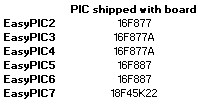
The 18F family MCUs are still 8-bit but offer a much wider 16bit instruction set, they are faster and have bigger RAM as you can gather from the following table. On the Microchip website you can find all the information you need and much more.


The dual power supply
EasyPIC5


EasyPIC6
The EasyPIC6 changed the power supply from a 7805 voltage regulator type to a switching one. On my EasyPIC5 I had to add a heatsink to reduce the temperature of the voltage regulator, reading Roman's article I realise it probably was common practice. The new switching power supply meant this problem was gone and
that the range of input voltages had also increased as shown in the table below.


EasyPIC v7
MC332690T3.3
With the EasyPIC v7 the power supply section has been further improved. There is now an additional crew terminal connector but most importantly you can now choose between 5v and 3.3v output voltages increasing the number of supported microcontrollers.


The mikroBUS

Mikroelektronika is putting quite some energy in promoting this new bus, many new Click boards compatible with  this novel "plug and play" connector. 
EasyPIC v7 mikroBUS
I find the mikroBUS to be quite interesting particularly considering the spreading use of shield-like boards that are now on the market. I am not entirely clear whether "shield" has been copyrighted just for the Arduino, reason for which others including Mikroelektronika have opted for alternative names, but these sockets are indeed very similar. It is quite nice to have piggyback modules like the Click boards. It is a really neat way to have the add on board built around its connector. It makes it look a lot more like a component to the main board than the previous accessory boards ever were.

Shield-like boards


Wrapping up

I think Mikroelektroinka has done overall an excellent job with the EasyPIC v7 in delivering a mature product, strong of many years of experience and of a large community continuously contributing to improve the board and its software platform.
The quality of the build is indeed very good, the attention to details and the look and feel are excellent.
Some things have left the board from the previous version, some have returned from the past, however the EasyPIC v7 is not simply an upgrade from previous versions instead its designers have managed to bravely approach a new layout which makes version 7 a complete shift towards a truly professional development board.