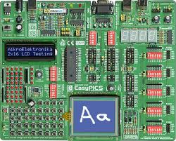
In this article I will review the new EasyPIC v7 development board from Mikroelektronika. I will compare it to the previous version, will look at the new design, take you through what is on board and what is no longer there and finally give you a general overview of it.
I really do not believe Mikroelektronika needs any more publicity on the EasyPIC v7, but I felt it would be nice to go through reviewing the new board my way and most importantly compare it with its predecessors!
Now, I am not going to compare them since the beginning of time, also because I jumped on board of the EasyPIC wagon only as of version 5, but I think it is nice to visually analyse the evolution of the board across the various versions it went through. Quite an impressive progression really! The quality of photography too :)
 |
 |
|
| EasyPIC2 | EasyPIC3 | |
 |
 |
|
| EasyPIC4 | EasyPIC5 | |
 |
 |
|
| EasyPIC6 | EasyPIC7 | |
Layout considerations
The designers of these great boards will hopefully forgive me if the considerations in this section may sound quite superficial, but I would first of all just give simply a visual impression of the various layouts without going in the details of why from an engineering point of view things were placed here or there. So with this in mind this is what I see:
It is interesting to notice how the various elements did and did not move from board to board. The layout of the EasyPIC2, 3, 4, 5 and 6 did not really change too much overall especially when compared to Version 7 which is without doubt the exception.
Led and buttons have always been bottom left but not in version 7 in which they have been placed in the ports area on the right.
The chip sockets more or less had been kept in the centre. One thing of note is that the EasyPIC5 as well as v7 have enough space for my trusty 40 pin zif socket to fit in. The EasyPIC6 would not allow it because the switch above the socket was really too close.
 |
| EasyPIC5, 6, 7 40 pin sockets side by side |
 |
| EasyPIC v7 with zif socket |
 |
| EasyPIC5 with zif socket |
The ports were top to bottom on the right, quite so in version 7 too but now you have two connectors and a proto header per port plus another connector per port on the left! No wonder, their theme for this version is connectivity!
The LCD spot of the EasyPIC 2 was taken by the GLCD in the EasyPICS 3,4,5 and 6 sending the LCD towards the top left area. I presume the GLCD was also the reason why the form factor as of the EasyPIC3 became bigger. Whereas the LCD is quite in the same place on version 7 too, the GLCD has taken the place of the buttons and led.
With regards to size wise apparently the boards are growing over time. The EasyPIC5 measured 25x21 cm, the EasyPIC 6 and v7 are both 26.5x22 cm.
The on-board programmer and the power section area made it to the version 7 keeping the same spot. Interestingly the on-board programmer has now a "warranty void if removed" shield. I am not sure I like it, even in the manual it is represented as a "black box". Could this be for copyright?
The external communication connectors have also kept their space exception made for the serial port which as of version 6 is in the top left corner.
The 7 segment display was "less lucky" it travelled quite a bit and at one point it made it off the board entirely. Welcome back in v7!
Similar sort had the DS1820 which every time was really placed where there was space left.
The AD converter trimpots have remained pretty much where they were from version 2 to 5 and to 6 although in this version one was removed. In version 7 they have been moved together with the other two trimpots for the GLCD and LCD in a column next to the displays area.
A more rational design
As you can understand by now, version 7 was quite revolutionary in its design. It grouped elements in functional areas much more than any of the previous versions and sacrificed some gadgets that were introduced in version 6, towards usability and a rational layout.
 |
| EasyPIC v7 |
 |
| EasyPIC6 |
 |
| EasyPIC5 |
I haven't used the new board too much yet but it looks to me that after a bit of readjusting my habits to the new layout it should be much easier to use. It shows some radical re-thinking of the board which must have taken some major effort and courage from Mikroelektronika. I am sure it will pay of.
Having port connectors to the left and to the right is really nice, you can now spread your work on each sides of the board. Often you have far too many things on the right of the board when you are working with complex projects and several accessory boards. Having port connectors on the left will surely help to have a much neater workbench.
What is and was on board

The new board comes with the usual PC keyboard, USB and serial port connectors and the Ext ICD provided as of version 6. A notable new addition is the new UART via USB based on the FT232RL chip. I would not be surprised to see the RS232 disappear from a future version 8 but I certainly hope it doesn't. Dinosaurs like me grew to love it and might be difficult to part from the good old connector.

According to him the perfect board should have had amongst other things:
2 AD converter trimpots as in the past versions
A piezo buzzer
An I2C eeprom
... and as if by magic you find all of the above on the EasyPIC v7! I couldn't agree more, those things were needed and are a welcome addition.
Another addition is the LM35 socket for an analogue temperature sensor, was it really needed? I am not entirely sure but if anything it is another way of using the ADC and it does not take too much space.

The theme of connectivity Mikroelektronika has provided the EasyPIC v7 with five time as many ways of connecting accessory boards, prototypes and what have you to their five base ports.
Five ways because each port headers is replicated twice on the right and once on the left of the board, plus on the proto connector. Last but not least the new mikroBUS sockets, something new and unique to this generation of boards.
 |
| EasyTEST |
 |
| EasyPIC v7 port group |
 |
| EasyPIC v7 mounting hole |
 |
| EasyPIC v7 GND point |
Anybody who has done any measurements on the previous boards would certainly welcome the additional GNDs point, this is something I have personally been waiting for. Much appreciated indeed.
| EasyPIC5 DIY spacers |
 |
| EasyPIC v7 plastic spacer |
The menu and the 4x4 keypads, the port expander and the COG display had short life. Newly introduced in version 6 they have already disappeared. Let me attempt to guess why that was and how can one live without.
 |
| EasyPIC6 keypads |
 |
| Keypad 4x4 board |

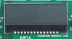 |
| EasyPIC6 COG |
 |
| EasyPIC v7 with COG |
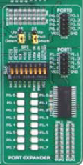 |
| EasyPIC6 Port Expander |
 |
| Port Expander Board |
 |
| Expand Click |
I hope by now I have convinced EasyPIC6 owners to upgrade to v7. The new board has a few element less than the previous one but all there was can be added if needed. Some of the things added to the current version are unique to it and make so that the board is more professional, usable and expandable than each previous version ever was.
The EasyPIC v7
I bought my EasyPIC v7 from MCU Store which is the UK distributor for Mikroelektronica's products and had a really nice and friendly chat with the owner Gavin, asking for his personal view on the new board in light of writing this article. He kindly provided a few good points, not a surprise giving his knowledge of this kind of products. Amongst his comments he pointed me to the EasyPIC6 review from Roman Black which I would really invite you to read and was an excellent source of material for this review.
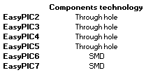
The EasyPIC6 introduced the SMD technology which contributed to a neater and more compact design. With the EasyPIC v7 this is taken to a further level. Click Boards are all SMD and through hole technology is gradually disappearing from the rest of the more traditional accessory boards.
How does it feel
 The board is build to last and gives the impression of being quite sturdy in general, the buttons feel nice to the touch, they make a clicking noise when pressed and are to me of better quality then in previous version. With regards to buttons, the reset has been moved to the top right corner of the board far away from other buttons and in my opinion in a better position to avoid pressing it accidentally.
 |
| EasyPIC v7 tristate switch |
I had to send back the first board I received because one of the trimpot knobs was broken, which can happen, but most annoyingly the LCD one was really quite loose and when measured it turned out to be faulty. The values on the ohmmeter where jumping all over the place when adjusting the resistance.The new board I received is fine but the trimpots still feel quite loose, maybe it is just a bad batch and hopefully the majority of the boards will be fine.
 |
| EasyPIC v7 dip switch |
Documentation
The documentation provided is, as always, of really good quality. Incredibly detailed and really easy to go through. For those who are not familiar with the board they would be able to get up to speed with it in no time.
In writing this review I have noticed however that for this version of the board there are practically no high resolution pictures like there were for the EasyPIC5. I think it is a shame it is no longer available and hope Mikroelektronika might reconsider adding it again.
 |
| EasyPIC5 Layout |
The schematic is absolutely excellent, I would really love if it were printed on a single page to "plaster" on the wall and keep as constant reference.
The package also includes a CD with all the software needed for you to start working with the board. To be in line with the excellent material provided in the box, all the software present on the CD I have received was up to date.
Some of the new aspects of the EasyPIC v7 have already been listed above, a radical new design , new components and the connectivity theme. Three of the most important new entries are however the 18F45K22, the dual power supply and the mikroBUS.
The 18F family
 Already with the EasyPIC6 there were examples for which the 16F887 had become too slow and too small. Back then the replacement of choice was the 18F4520 which in turn had replaced the 18F452. Moving to top range of MCUs I guess must have been on the horizon for some time and the new board embraces the 18F family as their default by shipping the board with an 18F45K22.
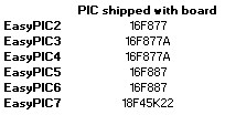
The 18F family MCUs are still 8-bit but offer a much wider 16bit instruction set, they are faster and have bigger RAM as you can gather from the following table. On the Microchip website you can find all the information you need and much more.

The dual power supply
 |
| EasyPIC5 |
 |
| EasyPIC6 |
that the range of input voltages had also increased as shown in the table below.

 |
| EasyPIC v7 |
 |
| MC332690T3.3 |
The mikroBUS
Mikroelektronika is putting quite some energy in promoting this new bus, many new Click boards compatible with this novel "plug and play" connector.
 |
| EasyPIC v7 mikroBUS |
I find the mikroBUS to be quite interesting particularly considering
the spreading use of shield-like boards that are now on the market. I am not entirely clear whether "shield" has been copyrighted just for the Arduino, reason for which others including Mikroelektronika have opted for alternative names, but these sockets are indeed very similar. It is quite nice to have piggyback modules like the Click boards. It is a really neat way to have the add on board built around its connector. It makes it look a lot more like a component to the main board than the previous accessory boards ever were.
 |
| Shield-like boards |
Wrapping up
I think Mikroelektroinka has done overall an excellent job with the EasyPIC v7 in delivering a mature product, strong of many years of experience and of a large community continuously contributing to improve the board and its software platform.
The quality of the build is indeed very good, the attention to details and the look and feel are excellent.
Some things have left the board from the previous version, some have returned from the past, however the EasyPIC v7 is not simply an upgrade from previous versions instead its designers have managed to bravely approach a new layout which makes version 7 a complete shift towards a truly professional development board.
4 comments:
Very nice review. Thank you for your detailed perspective.
I think anogher consideration is whether to go to the v7PRO or just stick with the V7.
With the layout of the V7PRO, it looks like there might be a way of someday having it accommodate 40pin (and smaller) devices. I'd go for that in a heartbeat.
Given they have renamed it EasyPIC Pro v7 from BIGPIC6, I would not be surprised if the EasyPIC v7 is the last EasyPIC we see. Btw in the "supported devices" section of the EasyPIC Pro v7 it says it can already work with 40 pin pics! I haven't seen an adapter though.
there is a bug in mikroBus, why they have connected both mikroBus sockets with same tx/rx? although PIC18F45K22 comes with two uart ports.
You are right Farrukh, I do not know if it is a bug or a "feature" but ... Milos proposes a workaround here http://www.mikroe.com/forum/viewtopic.php?f=12&t=54579&view=next
Post a Comment